|
||||||||||||
|
Home | ||||||||||||
|
||||||
|
|
||||||
|
Radio System |
||||||
|
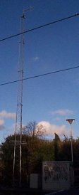
The radio system is vital to the effective running of the system and allows the Therapia Lane Control Room to communicate to a tram driver, to an operative on foot using a hand portable or to an operative driving one of the three road vehicles easily and clearly. The Tramlink radio system fully complies with MPT1323 and other trunked radio system protocols. However because Tramlink has only three frequencies (one of which is used for controlling the channel selection and base station operation) it is difficult to take full advantage of the system's capabilities. It is possible (but illegal) to listen in on Radio Scanners. Frequencies are reported to be on some Amateur Radio websites. |
||||||
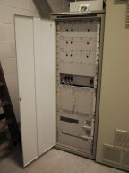
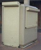
| Base Stations | ||||||
|
||||||
|
|
||||||
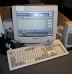
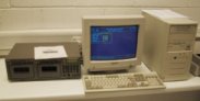
| In the Control Room | ||||||
|
||||||
| Radio Protocol | ||||||
|
Spelling is done using the 'Phonetic Alphabet' along with the acceptable abbreviations and keywords, as well as coded messages of a sensitive nature. Numerals are said individually, number '0' = Zero. Call signs are tram numbers, with each radio unit having an ID number for the control system to recognise. Radios are in each tram cab and are grouped together for a call received from the controller, i.e. "Tramlink Control to 2535". Once the response is received from the driver in A or B cab, then the group call is replaced by the channel opened by the tram radio. The controller speaks first in every exchange between the controller and the driver, as well as ending the exchange with 'Tramlink Control Out'. Each intermediate exchange ends in 'over'. |
||||||
| The Tram Radios | ||||||
|
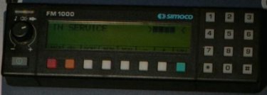
The radio in each tram cab is a Simoco FM1200 (not FM1000 as in this photo), complete with status LEDs, volume control, on/off button and numeric keypad. When the radio is on it displays the message 'In Service' and the strength of the control signal it is receiving. The unit is mounted in the centre of the drivers desk at the top.
There are a series of buttons along the bottom of the display: -
In addition, the Left hand foot pedal is used for Radio communication too. If a driver wishes to contact Control under normal circumstances, he either presses the foot pedal or the Green Button to request control to call them back. The Tram Number and the Driver's Name comes up on the Computer with an audible warning. The Controller then touches the correct part of the screen and the driver will hear a ringing tone from the speaker. The driver then has to press the foot pedal to open the channel. A Green status LED (above the volume control) is lit when a Radio Channel is Open. A Red status LED (also above the volume control) is lit when the Driver is talking. An Amber status LED (also above the volume control) is lit with an audible warning when the signal strength is so low it has lost contact with a base station. These LED's are in a common cluster, green on the left, amber in the centre and red on the right. |
||||||
| Emergency Calls | ||||||
|
These are made by pressing the Red button on the radio. This call then takes priority over any other calls waiting to be answered by the controller and can't be accidentally deleted from the display. When the controller responds, the driver is required to give the following information: -
The controller will then carry out the procedures required and then confirm to the driver the actions that have been taken. |
||||||
| Group Calls | ||||||
|
These can be made to all radios for announcements and if the controller requests each tram to acknowledge the announcement, then the amber button on the radio is pressed to confirm the message was received and understood. |
||||||
| Status Messages | ||||||
|
The controller and driver have the ability to send status messages to each other. This is so that standard messages, such as driver changes can be sent quickly without the Radio Channel being occupied whilst the message was spoken. The number of status messages is fixed and each message has an identification number. There are 23 available between the driver and control and 5 between control and the driver. Each message is no more than 16 digits long. When control sends a status message to the driver, an audible tone sounds and the text message appears on the radio. The driver would acknowledge the message then clear it from the radio. The driver sends a status message by pressing the white status button on the radio, choosing the required message by scrolling up or down using the + and - buttons and then sending the message by either pressing the foot pedal or by pressing the # button on the keypad. |
||||||
| Voice Recorder | ||||||
|
||||||
| Evacuating the Control Room | ||||||
You can also talk directly from tram to tram, but this is rarely used as it would also occupy a radio channel through the control room and drivers are not taught everything the cab radio's are capable of. There are 48 code numbers, one for each tram cab, so if you wanted to call 2539A from 2551B you could key in a 3 digit number (not related to the tram number) and the radio in cab A of 2539 would ring and display the code for 2551B, once the call had ended then the person in 2551B would have to close the channel by pressing * # . This method of communication was used a lot during testing of the signalling system before opening. It is also possible (or was until the facility was blocked) to make a telephone call from a mobile or hand portable unit because the radio system is tied in with the PABX (Telephone Exchange). However once one frequency is in use only one other is available for traffic and thus allowing mobile units to make phone calls would cause problems. If two units were to make calls that would tie up the whole radio system until the calls ended. Whilst useful in some circumstances, it is open to abuse and has to be used with caution which is why the facility was blocked. |
||||||
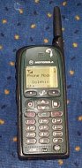
| Dolphin Handsets | ||||||
Many thanks to everyone who has helped with the information on this page. |
||||||
|
|
||||||
| Designed by Trapdoor Internet Services |