|
||||||||||||
|
Home | ||||||||||||
|
|||||
|
|
|||||
|
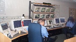
The Control Room |
|||||
The control room is on the top floor of the depot at the West Side and overlooks the stabling yard. There are four main functions supervised by the Control room: -
|
|||||
|
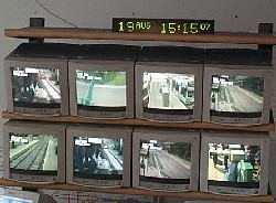
CCTV and Help Point monitoring |
|||||
Each tram stop has at least one CCTV camera that allows the controller to view the entire platform area and if a public help point is pressed will automatically display on the controllers screen. This is used to talk to a member of the public in an emergency. The controllers also have a bank of monitors available to them which rotates through each camera every so often, but can be set to one location should the need arise. Controllers can activate recording of any camera as well as controlling its direction. When a help point is pressed, the camera will automatically zoom in on the Help Point and activate recording. Cameras are configured to pan and tilt past certain areas of view when moved, e.g. residential buildings, etc, for reasons of privacy. The cameras are vital to controllers to monitor trouble as it happens and record evidence if required. The system is likely to be upgraded in the future to provide better coverage, possibly including cameras onboard trams as well, and also to record continuously. |
|||||
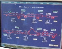
| Power Supply Control | |||||
The power supply to the overhead lines and tram stops is controlled by a SCADA (Supervisory Control and Data Acquisition) system. By changing the screen display, controllers can see a display of various parts of the power supply circuitry. All section isolators and breakers are shown and sections can be isolated at the click of a mouse if required. See the Electrification System page for more information. |
|||||
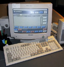
| Radio Communications | |||||
The control of the radio system is by using the touch screen dispatcher. This allows the rapid answering and making of calls. Incoming calls and status messages are displayed on the screen together with the tram number and drivers name. Emergency calls are given a higher priority and must be answered first. All radio calls timeout after about two minutes to ensure they are not used for unnecessary conversation. Please see the Radio System page for more information. |
|||||
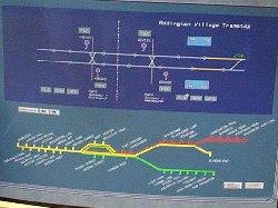
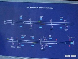
| Signalling Control and Service Regulation (Tram Management System - TMS) | |||||
Basically this system displays the track system in a schematic form with the location of the signals, points and tram stops indicated. A tram is identified by it's fleet number and the duty it is working. On the TMS screen a tram is shown by a yellow coloured line overlapping the lines depicting the track. As the tram passes over a loop its position is updated on the display. The controller can click on a tram stop on the overview and get a detailed display of the tramstop. From here he can interrogate the status of each loop, point and equipment cabinet associated with the tram stop. Ticket Vending Machine (TVM) alarms and Passenger Information Display (PID) messages can also be accessed using these schematics. The TMS also allows the Controller to instigate remote phase requests should the loop not have detected a tram approaching the junction automatically. The trams onboard computer (VECOM) tells the system where the tram is and if it is early, late or on time at any given moment. This is done by control loops between the track. Once the information from each tram is in the system, it can send out information such as the time before the next tram is due and it's destination at the tram stops up the line, as well as say changing the sequence of the trams around the town centre loop should one tram be running late. A warning can be given to the controller who may then decide to turn a tram short to get it back on schedule, if it is unlikely to make up the time by the time it reaches the next terminus. For more information, please see the Signalling or Passenger Information Display pages. |
|||||
|
|
|||||
| Designed by Trapdoor Internet Services |